One in ten aerospace parts today moves from prototype to production in under a week—a startling pace that changes how teams plan cost, time, and procurement.
You need repeatable accuracy for flight hardware and industrial components. Modern cnc machining delivers that repeatability for metals and rigid plastics, so your parts meet tight tolerances and functional testing.
In this article you’ll learn how to evaluate a provider’s capabilities—certifications, inspection options, and traceability—so your program stays on schedule. We’ll define practical precision limits, from general +/- 0.005″ to sub +/- 0.001″ when GD&T and setups permit.
You’ll also see typical size envelopes for milling and turning, surface and edge expectations, and simple sourcing checks that reduce risk. By the end, you’ll have a buyer-focused framework to turn engineering design into executable manufacturing plans.
What Buyers Need to Know Now about Metal CNC Machining
Buyers today must match design intent to realistic shop capabilities to avoid costly rework.
If you source prototypes or production, expect streamlined digital quoting that includes DFM feedback, pricing, and lead times. Automated reviews flag thin walls, deep pockets, and tool access issues before a job starts.

Insist on documented quality early in the RFQ—inspection levels, material certs, and Certificates of Conformance remove ambiguity. For aerospace or medical work, qualify suppliers with AS9100D or ISO 9001/13485 to ensure process repeatability and traceability.
- Set tight tolerances only where function demands; use general tolerances elsewhere to save cost and time.
- Ask if the shop has experience with your materials—aluminum, stainless, titanium, or nickel alloys—to reduce tooling rework.
- Confirm the partner can scale orders, control revisions, and protect sensitive surfaces during handling and shipping.
- Lock thread specs, inserts, and assembly notes up front—these affect toolpaths and lead times.
Share 3D CAD with GD&T, finish callouts, and inspection expectations to smooth the transition from design to shop. That simple step speeds cnc machining work and improves final part quality.
Understanding the Manufacturing Process: From CAD to Cut Part
A clear digital thread turns a 3D design into repeatable movements on the shop floor.
You begin by uploading a CAD model. A DFM review flags undercuts, minimum feature risks, and inaccessible faces before programming starts.
CAM translates geometry into toolpaths, then into precise G-code that tells the machine feeds, speeds, and tool changes. That G-code is the bridge between design and production.

Setup, tools, and fixtures
Plan setups that maximize access. Five‑axis and 3+2 strategies often machine multiple faces in one setup, which cuts re‑fixturing and cycle time.
Multitasking mill‑turn centers with live tooling add axial and radial features without moving the part. That reduces error and speeds throughput—sometimes enabling lead times as fast as 3 business days.
- Select standard end mills, drills, taps, and boring tools when possible—fewer unique cutters shorten setup time.
- Design soft jaws or dedicated fixtures to hold thin walls without distortion—better fixturing improves accuracy and surface consistency.
- Check minimum feature size early—many shops use ~0.020″ as a baseline to avoid tool breakage.
| Focus | Typical Value | Why it matters |
|---|---|---|
| Default surface | ~125 Ra (as‑machined) | Acceptable for many parts; specify secondary finish when needed |
| Minimum feature | ~0.020″ | Prevents thin‑wall failures and broken tools |
| Quick turn | 3 business days | Speeds prototype and low‑volume production |
Pair clear drawings with GD&T for key datums. That improves first‑article success and aligns inspection plans with program intent.
Metal CNC Machining Processes and Machine Types
Machine selection—matched to part geometry—starts every successful production run.
Choose 3‑axis mills for prismatic parts and simple profiles. Use 3+2 setups to index multiple faces in one clamping and reduce handling.
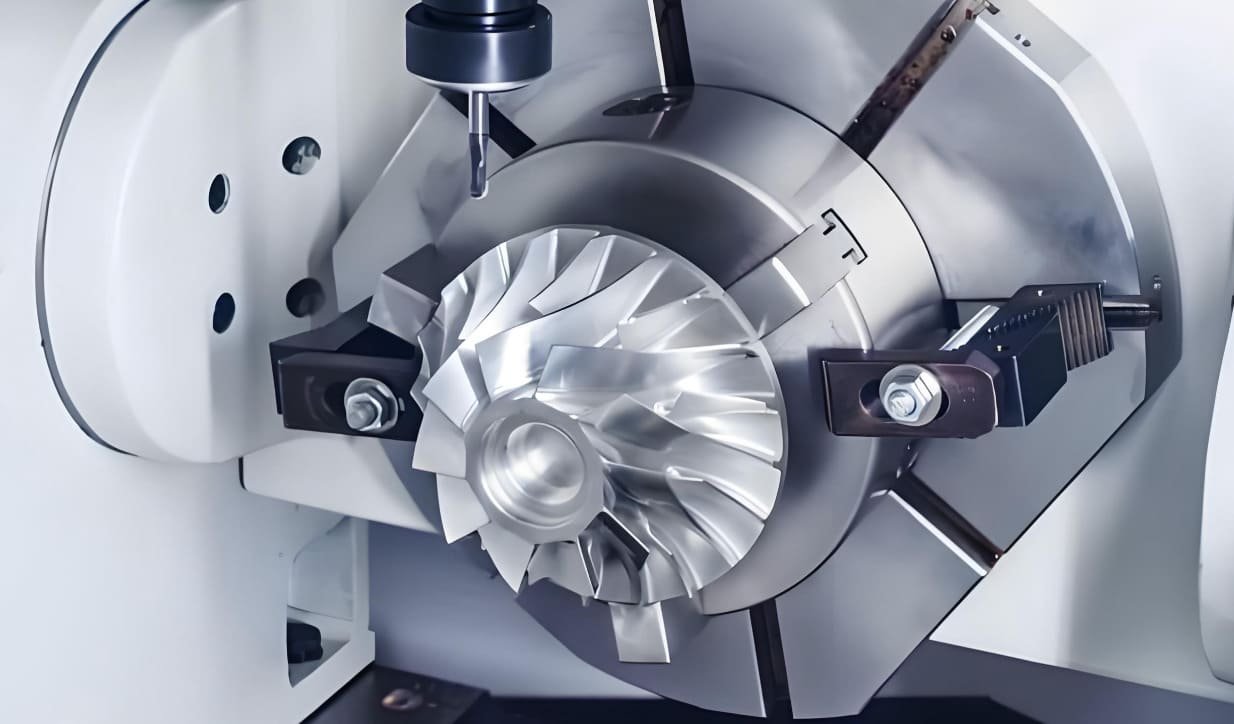
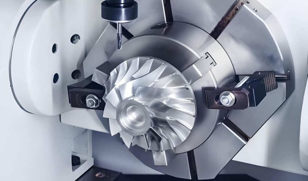
Reserve 5‑axis machines for freeform surfaces, impellers, and features with limited access. Multitasking mill‑turn centers with live tooling cut axial and radial holes, flats, grooves, and slots without re‑fixturing.
Milling, Turning, and Secondary Operations
Turning is ideal for cylindrical parts; mill‑turn combos add side operations in a single cycle. That lowers cumulative error and shortens cycle time.
- Drilling → boring for precise holes; tap or thread‑mill to finish threads.
- Grinding delivers top surface finish and accuracy—slower, but necessary for bearing fits.
- Sawing sizes stock; broaching produces keyways and splines at volume (higher up‑front cost).
| Process Type | Common Use | Benefit |
|---|---|---|
| 3‑axis milling | Prismatic parts | Simple setup, lower cost |
| 5‑axis milling | Freeform surfaces | Single‑setup access to complex geometry |
| Mill‑turn (live tooling) | Cylinders with side features | Fewer re‑fixtures, improved accuracy |
Document required secondary ops and workholding on your drawing. That aligns programming, tooling, and inspection from the start and keeps production predictable.
Materials That Matter: Metals for Strength, Corrosion Resistance, and Wear
Material choice drives cycle time, tool life, and final part performance—pick wisely for reliable production.
Aluminum options
Use 6061 for economical, general-purpose parts with good machinability. Choose 2024 when fatigue resistance matters. For high strength, specify 7075. Select MIC-6 when flatness and dimensional stability are priorities.
Stainless and high-strength steels
Pick 303 for easier cutting, 304/18-8 for general corrosion resistance, and 316/316L for marine or medical use. For higher tensile strength, use 17-4 or 15-5 after heat treat. For shafts and gears, consider 4140/4140PH or 4340; 1018 works for low-cost parts.
Titanium, copper, and exotics
Specify Grade 5 (Ti-6Al-4V) when strength-to-weight is critical; Grade 2 when corrosion resistance dominates. Use C110, 360 brass, or C932 bronze for conductivity and low friction. For high-temp or corrosive environments, select Inconel, Monel, Hastelloy, or zirconium—expect slower machining and higher tool wear.
- Call out tempers and certs on drawings.
- Match grade to function to avoid overpaying for unnecessary alloys.
Plastics in a Metal-Centric Workflow: Fixtures, Insulators, and Hybrid Builds
Plastics play a key role when you need protection, insulation, or lower weight without redesigning an assembly.
Common CNC plastics—ABS, acrylic, acetal (Delrin), HDPE, Nylon 6/6, PC, PEEK (including GF30 and USP Class VI), PP, PTFE, UHMW, PVC, and ULTEM 1000/2300—bring a wide range of properties to production work.
PEEK, PC, Nylon, PTFE, ULTEM: properties and resistance
PEEK offers high-temperature performance, wear resistance, and excellent chemical resistance—often a metal substitute for weight or dielectric needs.
ULTEM delivers strong dielectric properties and continuous high-temp service for aerospace and medical uses. PTFE gives extreme chemical resistance and the lowest coefficient of friction—ideal for bushings and seals.
PC works well for impact-resistant windows or guards, while Nylon balances toughness and abrasion resistance for lightweight parts.
Where plastics outperform metals
Use plastics for fixtures, soft jaws, and insulators to protect finished surfaces and ensure repeatable setups. Lining jaws with UHMW or Nylon pads lengthens fixture life and protects critical finishes.
- Typical tolerances: ±0.010″—account for higher thermal expansion and potential creep.
- Combine plastics with metal substructures for hybrid builds—plastics provide insulation or low-friction surfaces while metals supply strength.
- Request resin certs for regulated programs—material traceability matters in aerospace and medical production.
- Machine polymer features faster than many metals—use that speed to lower cycle time on non-structural parts.
Tolerances, GD&T, and Tight Tolerances for Aerospace-Grade Parts
Dimensional strategy—where you save and where you spend—drives cost and lead time.
Set general tolerances for noncritical features and reserve sub ±0.001″ only for functional interfaces. For most metals use ±0.005″; for plastics allow about ±0.010″. This approach limits time and tool wear while protecting key fits.
Minimum features, threads, and tapped holes
Respect minimum feature sizes—around 0.020″ depending on geometry and material—to avoid tool breakage and poor finishes. For threads, call out class and depth up front; aim for 1–2× diameter thread engagement or specify inserts for soft base material.
Holding flatness and tight tolerances at scale
Flatness over large surfaces is hard. Use thicker sections, ribs, split large plates, or stress‑relieved stock to improve results. Toolpaths, in‑process probing, and post‑machining stress relief also help hold precision across runs.
“Control datums, flatness, and true position with GD&T to specify function rather than manufacturing steps.”
Plan inspection: first article reports, sampling, and in‑process checks reduce risk in production. Machine related features in a single setup—3+2 or 5‑axis strategies—cut stack-up and boost repeatability.
Surface Finish and Post-Processing Options for Performance and Aesthetics
Select finishes that match function, environment, and budget—cosmetic needs differ from wear and corrosion demands.
Quick, as‑machined options
Choose as‑machined when speed and low cost matter. Expect ~125 Ra and visible tool marks unless you specify secondary deburr or bead blast.
Tumbling removes burrs and softens edges; bead blast gives a uniform matte look for cosmetic parts heading into production.
Anodize, hardcoat, and PTFE options
Type II anodize (MIL‑A‑8625 Type II) improves corrosion resistance and looks. Type III hardcoat adds wear resistance for sliding surfaces.
For sliding parts, PTFE‑impregnated hard anodize (AMS‑2482 Type 1) offers self‑lubrication and longer service life. Consider titanium anodize (AMS‑2488 Type 2) to help fatigue life on titanium components.
Stainless, chem film, electropolish, and platings
Chem film (MIL‑DTL‑5541) gives thin corrosion protection and conductivity on aluminum. Passivate per ASTM A967 to boost stainless steel corrosion resistance without changing dimensions.
Electropolish (ASTM B912) eases micro‑roughness in fluid systems. Use electroless nickel, silver, gold, or zinc per MIL/ASTM specs when conductivity, solderability, or extra barrier is needed.
| Finish | Typical Effect | Best Use |
|---|---|---|
| As‑machined / Bead blast | ~125 Ra / matte appearance | Fast prototypes, cosmetic uniformity |
| Type II / Type III anodize | Corrosion protection / high wear resistance | Enclosures, wear surfaces |
| PTFE hard anodize | Low friction, extended life | Sliding guides, actuation interfaces |
| Electropolish / Plating | Reduced micro‑roughness / conductivity | Fluid contact, electrical finishes |
Plan finishes early so masking, fixturing, and dimensional changes are built into your design and cost estimates. Document Ra targets, edge breaks, and masked areas on drawings to improve repeatability for cnc parts and precision production.
Certifications, Compliance, and Inspection Options Buyers Should Demand
Certifications and inspection plans define how a supplier proves capability and protects your program.
Require clear evidence of quality systems and export controls before you award work. Prioritize AS9100D for aerospace and ISO 13485 for medical programs to show process maturity and regulatory alignment.
Ask for ITAR registration if your program touches defense data or restricted technical information. ISO 9001:2015 and IATF 16949:2016 add confidence for high-volume or automotive supply chains.
Inspection scope, traceability, and deliverables
Define inspection from the start—standard checks, first article inspections (FAI), and full dimensional reports where required. Require material certifications and Certificates of Conformance (CoC) to match specs and POs.
- Trace serialized or safety-critical parts to heat lots and inspection records.
- Use in-process probing, tool monitoring, and final CMM verification to hold precision across runs.
- Confirm calibration records for gages and CMMs to ensure measurement validity.
- Include packaging notes—ESD, cleanroom bags, or rust inhibitors—on the PO.
| Certification | Why it matters | When to require |
|---|---|---|
| AS9100D | Demonstrates aerospace-quality systems and traceability | Flight hardware and safety-critical components |
| ISO 13485 | Aligns processes to medical device regulatory needs | Medical implants, surgical tools, and sterile assemblies |
| ITAR / ISO 9001 | Controls export of defense data; shows general QMS maturity | Defense contracts and regulated manufacturing programs |
| IATF 16949 | Automotive supply chain controls and continuous improvement | High-volume automotive production |
Mitigate risk by aligning your quality plan with the supplier’s QMS before release. Audit document control and change management when revision integrity matters to your program.
Capacity, Lead Times, and Part Sizes That Influence Your Timeline
Lead time and shop capacity often decide whether a part ships on schedule or slips weeks.
Plan quick-turn slots for prototypes—standard lead times can be as fast as 3 business days for simple work. For production ramps, use forecasted orders or blanket POs to lock capacity and lower risk.
Design within machine envelopes. Typical maximums are milled parts up to 80″ × 48″ × 24″ and lathe parts to 62″ length by 32″ diameter. Very large pieces may need segmentation and assembly to fit machines and reduce handling time.
Quick-turn prototypes to high-volume production
Reserve finishing vendors early and pre-approve standards so parts don’t queue. Limit special cutters and minimize setups—consolidated ops run faster.
- Use standard stock sizes and request kitted stock for repeat orders.
- Reserve long-lead alloys early to avoid supply bottlenecks.
- Request partial shipments by feature completion when helpful.
Maximum part envelopes for milling and turning
Balance precision and schedule—tighter tolerances and complex finishes extend cycle time. Define inspection lead time in quotes; FAIs and special testing add days and should sit on your critical path.
| Focus | Value | Why it matters |
|---|---|---|
| Quick turn | 3 business days | Fast prototypes, faster feedback |
| Milled envelope | 80″ × 48″ × 24″ | Plan one-piece vs. assembly |
| Lathe envelope | 62″ L × 32″ Ø | Large turned shafts or housings |
Design for Manufacturability: Proven Tips to Reduce Cost and Risk
Designing with straightforward access and standard tools keeps cost and schedule predictable. Early DFM cuts hidden complexity and makes production repeatable.
Corner and floor fillets, undercuts, and access
Add corner radii about 0.020″–0.050″ larger than drill radii so common cutters clear without special tooling. Use smaller floor fillets than wall fillets so one tool can clear a pocket and evacuate chips.
Standardize undercuts and place them away from tight corners. That keeps tool paths simple and reduces time spent on custom fixturing.
Tall walls, thin sections, deep pockets, and deep holes
Avoid tall, thin walls and deep narrow pockets—tool deflection will hurt surface finish and accuracy. Add ribs or split large parts to stiffen sections.
For holes, keep depth below about 5–6× diameter when possible. If you must go deeper, add cross‑holes or peck drilling to manage chips and reduce breakage.
Text and cosmetic features: When they add time and cost
Raised text and deep engraving increase cycle time and tooling wear. Use laser marking or labels for cosmetic or serialized marks when function allows.
| Design Area | Recommended Guideline | Benefit |
|---|---|---|
| Corner fillets | 0.020″–0.050″ above drill radius | Use standard tools; fewer special cutters |
| Floor fillets | Smaller than corner fillets | One tool clears cavity; better chip flow |
| Hole depth | < 5–6× diameter preferred | Faster drilling; lower tool breakage |
| Text/engraving | Prefer laser marking over deep engraving | Lower cycle time; reduced tooling wear |
Document allowable edge breaks and surface targets on drawings. Allow tool runout beyond tapped depth for full threads and group common hole sizes to cut tool changes and programming time.
Metal CNC Machining vs. 3D Printing and Injection Molding
Selecting the right manufacturing route means trading geometry freedom, material performance, and per-part economics.
Subtractive work delivers higher dimensional accuracy and isotropic mechanical properties compared with many additive systems. That matters when you need consistent strength, wear resistance, or corrosion resistance across a part.
3D printing wins on geometric flexibility and fast iteration. It is ideal for complex internal channels or quick design checks. Expect compromises in surface finish and tight tolerances for many printed processes.
When CNC wins on speed-to-quality for production parts
Use machining when tolerances, surface quality, and material properties must be production-grade across all axes. You can often get quick-turn parts the same day in optimized workflows.
Injection molding becomes the best option once volumes justify tooling. It offers the lowest per-part cost at scale and molded-in features that reduce assembly steps.
- Choose 3D printing for complex geometry and rapid prototypes—accept trade-offs in finish and repeatability.
- Pick machining for final parts that need full-strength, corrosion resistance, or high-precision faces and threads.
- Use injection molding for thousands of identical parts after you amortize tool cost.
- Combine processes—print for speed, then machine critical interfaces to reach time-to-quality faster.
Industry Applications: Aerospace and Industrial Use Cases
Real-world applications — brackets, housings, and bearings — force you to balance strength, weight, and corrosion resistance.
Brackets, housings, gears, bearings, and internal components
You’ll machine common parts such as housings, brackets, gears, and bearings for aerospace, medical, and automotive work.
Use 7075 or 6061 aluminum for bracket and housing work when strength-to-weight and quick production matter.
Choose 4140 or 4340 steel for shafts and gears where toughness and fatigue life are critical—add grinding for final fits.
Material selection tied to corrosion, wear, and high impact environments
Specify 17-4 stainless or 15-5 for high-strength, corrosion-resistant actuator components and linkages.
Pick titanium Grade 5 for weight-critical or high-temperature uses, and Inconel or Monel for exhaust, turbine, or marine service.
“Match alloy choice to environment—chlorides, heat, and chemicals demand specific resistance and inspection plans.”
- Design bearings and wear pads in bronze or PTFE-coated aluminum for low friction.
- Plan serialized traceability and FAIs for flight hardware; use standard inspection for noncritical assemblies.
- Standardize a core set of alloys per program to simplify supply and speed qualification.
Digital Quoting, DFM Feedback, and Order Workflow in the Present Day
Digital quoting shortens the gap between design and production by wrapping pricing, manufacturability checks, and scheduling into one fast workflow.
Instant pricing, lead time, and manufacturability guidance
Upload your CAD to get immediate pricing, lead times, and an automated DFM that flags thin walls, inaccessible radii, and risky features.
You can iterate designs quickly—apply DFM suggestions, regenerate quotes, and compare options in minutes.
At order time you lock drawings, GD&T, finish callouts, inspection levels, and material cert requirements so the shop programs to your specs.
From quote approval to machining to finishing and shipping
Track order status through machining, finishing, and outbound logistics to reduce schedule risk.
- Consolidate milling, turning, and finishing into a single workflow for clearer accountability.
- Select inspection upgrades and traceability at checkout so metrology is planned up front.
- Pre-approve alternate finishes or materials to avoid delays when supply tightens.
- Save BOMs, approved finishes, and inspection templates for fast repeat orders.
- Use partial shipments to align deliveries with downstream assembly and shorten program time.
“Compare delivered parts to model intent and feed findings back into tolerances and finish choices for the next run.”
Threading and Features: Best Practices for Strong, Reliable Assembly
Correct thread form and depth are small design choices that prevent big assembly failures.
Model threaded holes at the recommended core or tap drill diameter and call out the thread form—UNF, UNC, or metric—on the drawing. That tells the shop how to size holes and which cutting tools to prepare.
Specifying threads, depths, and inserts for metals and plastics
Keep thread depth near 1–2× the nominal diameter for reliable engagement and to limit tap breakage. Deeper threads add cycle time and risk.
- Specify thread class (H2 is common; H3 is tighter and costs more).
- Use thread milling for fragile materials or odd sizes; tapping is faster for standard internal threads.
- Consider Heli‑Coil or key inserts to strengthen threads in aluminum and plastics—note many shops do not supply or install inserts by default.
- Prevent partial threads by giving clearance past the tapped depth—add a counterbore or relief for tool runout.
- Call out external threads explicitly; milled components sometimes require special turning or secondary ops.
Align fastener standards across your assembly to cut program complexity and simplify inspection. Document gauging, lubrication, and locking methods so acceptance matches assembly needs.
“Model threads correctly, call class and depth, and plan inserts up front—small notes save time and reduce field failures.”
Metal CNC Machining: Key Buying Criteria, Costs, and Risk Controls
Selecting a supplier starts with matching their equipment and quality systems to your program goals.
Choosing the right partner
Vet machine mix first—5‑axis and mill‑turn capability shortens setups and raises precision for complex parts. Check experience across alloys from aluminum to nickel‑base alloys and stainless steel grades.
Require proof of quality systems: AS9100D, ISO 9001 or 13485, IATF 16949, and ITAR when defense data is involved. Ask for material certs, traceability, and planned inspection steps up front.
Cost drivers and risk controls
Tighter tolerances, complex geometry, exotic materials, and special tools raise time and price. Minimize cost by simplifying design—standard radii, fewer setups, and realistic tolerances.
Control cycle time by reducing tool changes and avoiding non‑standard cutters unless function requires them. Balance finishes—hard anodize, passivation, or plating—against corrosion and wear resistance to avoid late surprises.
“Set PPAP‑style gates: FAIs, capability checks, and in‑process probing for critical features.”
- De‑risk with inspection plans and serialized traceability.
- Model total landed cost including finishing and inspection lead times.
- Use multi‑sourcing for surge volume but centralize revision control.
Conclusion
Finish strong: pick partners and specs that turn drawings into dependable production parts.
Choose a certified supplier with the machines, materials expertise, and inspection plan to meet aerospace and industrial demands. Set tolerances where function matters, and call finishes to standards so surface and corrosion resistance match the environment.
Use digital quoting and DFM feedback early—this cuts cost and shortens lead times. Plan capacity, envelopes, and hybrid builds so parts and fixtures fit schedules and assembly flow.
Standardize materials, threads, and finishes across programs. Do that and you’ll turn clear specifications and GD&T into repeatable, precision production that delivers parts on time and on spec.